-3.png?height=120&name=MecaLogo-Black%20(1)-3.png)
This MecaNetwork example discusses the basic integration of the Bota systems 6-axis force torque sensor with the Meca500 industrial robot.
|
|
 |
 |
 |
-3.png?width=335&height=96&name=MecaLogo-Black%20(1)-3.png)
The use of both components is greatly simplified by the possibility to communicate over EtherCAT and to configure the sensor using CANopen over EtherCAT (CoE).
It is possible to purchase a Meca Kit directly from Bota systems, containing all necessary components and connections to jumpstart the integration with the Meca500.
Furthermore, the sensor is extremely advantageous for direct flange assembly, as it's low weighs leaves ample spare payload for the Meca500.
A Beckhoff TwinCAT3 example is available in the MecaNetwork, detailing on how to control the robot's movements in TwinCAT3.
This article presents the general steps in order to connect the Meca500 and the Bota systems Rokubi (which has been replaced by the new MiniONE Pro FT sensor) to an industrial PC (Beckhoff PLC in the example), and to visualize the real-time data output from the sensor.
Integration examples are available on the Bota website.
TABLE OF CONTENTS
- Components
- Technical specifications of the Rokubi sensor
- Assembly
- TwinCAT3 setup
- Real-time sensor data
- Attachments

Components
- Meca500 industrial robot: Go to link
- Meca500 firmware version 8.1.6 or above required: Go to link
- Beckhoff C6015-0010 PLC (or similar) : Go to link
- TwinCAT3 (XAE Shell or Visual Studio extension) : Go to link
- See this MecaNetwork example of Beckhoff-TwinCAT3 integration
- Allen Bradley 24V Power supply (or similar): Go to link
- RJ45 cables
- Bota Systems Force Sensors
- Bota Systems Medusa multi-axis Force Torque sensor: Go to website
-
- Bota systems MiniONE Pro FT sensor: Go to website
- Tool adaptor for the sensor with the Meca500 flange pattern;
- Sensor adaptor to mount the sensor on the robot;
- Sensor cable and EtherCAT cable;
- Power supply cable or AC power adaptor:


Technical specifications of BOTA sensors
MiniONE Pro FT Sensor Kit
-
Plug & Work
-
Retrofits on your current robot
-
Fast installation
-
Highest force sensitivity
-
Compact & Lightweight
-
Outstanding drift performance
-
IMU measurements*
-
Inertia compensation*
-
Ideal for force feedback applications
* EtherCAT version only
Medusa sensor
- Compact and lightweight
- High impact robustness
- EtherCAT or Serial protocol
- Integrated with 6 DoF IMU
- Internal temperature sensor
- Rated IP67
- Up to 1000 Hz update rate
- Range (Fxy, Fz, Mxy Mz): 400 N, 500 N, 5 Nm, 8 Nm
- Noise level better than 0.01% of nominal range
- Weight: 110g
- Size (D x L): 48 x 32 mm

Assembly
Preparing the Meca500
- Connect the Meca500 as usual to the power supply and your PC. For detailed instructions on how to do that, please refer to this Quick Reference Guide.
- Open the web interface of the Meca500 and connect the robot, without activating of homing it.
- In the programming panel, enter the command SwitchToEtherCAT and execute. This command will switch the Meca500 from TCP/IP to EtherCAT communication protocol. For details on how to use the web interface, please see this video.
- Disconnect and power off the Meca500.
Mounting the Bota systems sensor
| Install the Bota systems sensor mounting bracket on the Meca500's flange using four M3 screws. Take note of the two dowel pins, used for aligning the sensor on the bracket. |  |
| Install the Bota systems sensor on the mounting bracket using M3 screws. Use the dowel pins, mentioned above, to align the bracket and the sensor. | 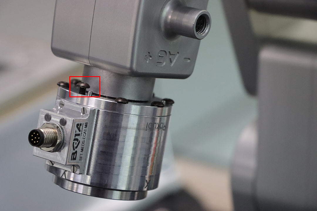 |
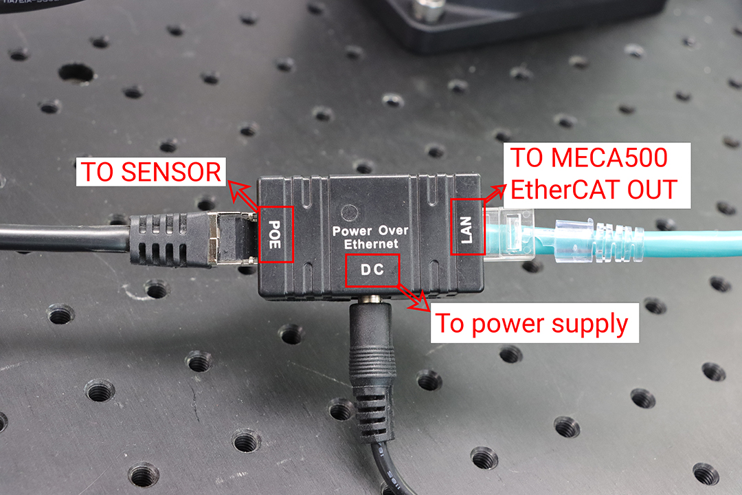
| Connect the Bota systems sensor to the PoE adaptor (POE-marked socket) (M12 to RJ45). |  |
 |
|
| Connect the PoE adaptor's LAN port (RJ45) to the Meca500's EtherCAT OUT port (M12 industrial connector). |  |
| Power the PoE adaptor with the provided power supply. You might need to use an adaptor for the Europlug. |  |

Connecting to the PLC
| Connect the Meca500's EtherCAT IN port (M12 industrial connector) to the Beckhoff PLC's LAN2 (X103) port (RJ45). | 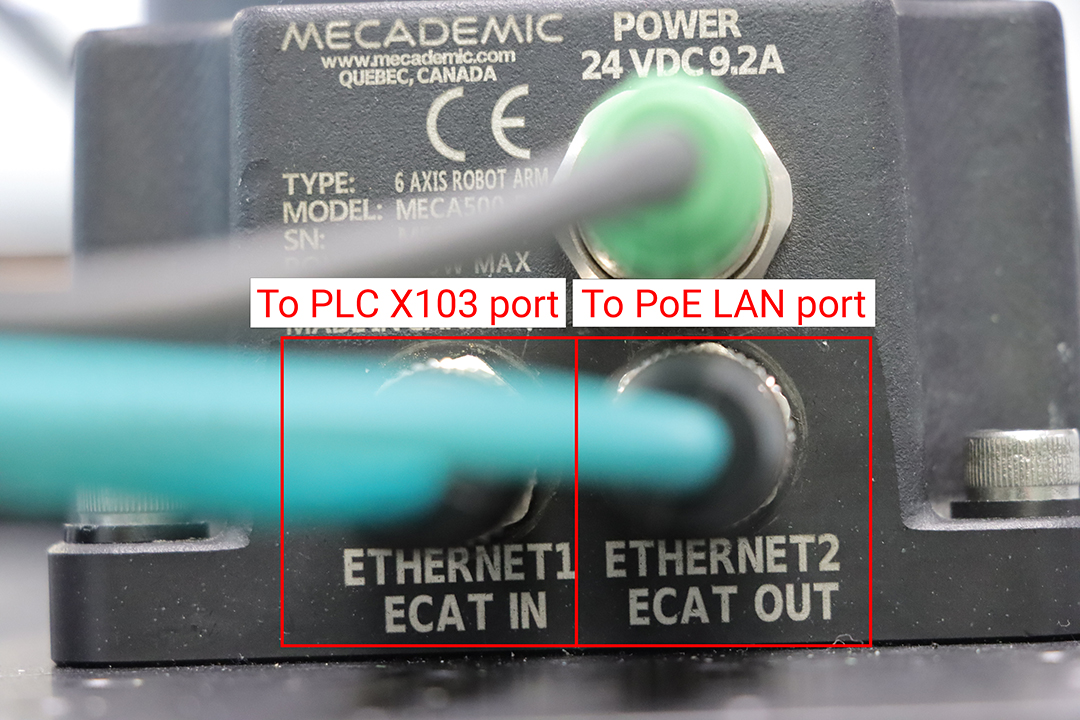 |
 |
|
| Connect the Beckhoff PLC's LAN1 (X102) (RJ45) port to your PC's Ethernet Port (RJ45). | 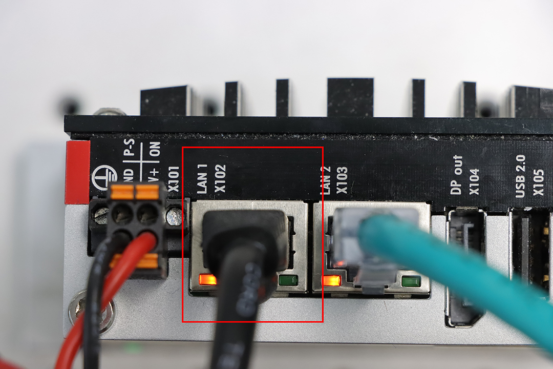 |
| Connect the Beckhoff PLC to the 24V power supply using two jumpers or two pieces of stripped wire. The 24V+ port (Beckhoff PLC) goes to the (or one of the) 24V+ power supply port. Similarly, the GND port (Beckhoff PLC) goes to the (or one of the) "-" ports of the power supply. | 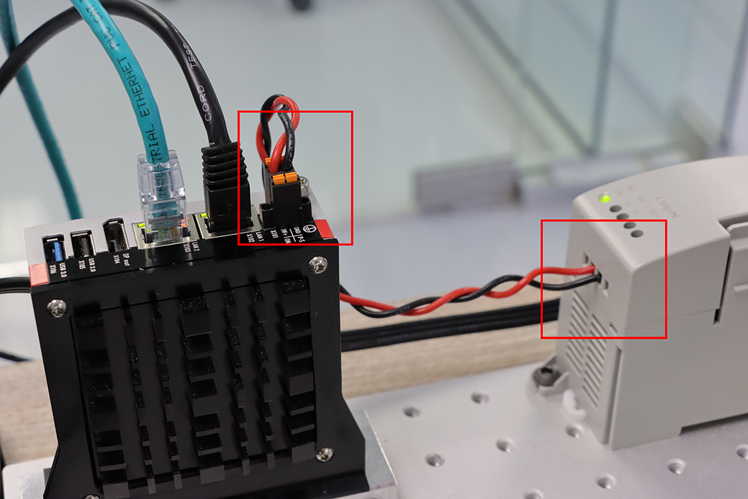 |
| Power the 24V power supply and make sure that the PWR LED on the Beckhoff PLC emits steady green light. | 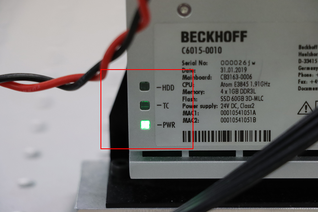 |
TwinCAT3 setup
For this example, we will use Visual Studio 2019 with a TwinCAT3 extension.
Using the TwinCAT3 XAE Shell will result in the same steps and manipulations.
The Visual Studio - TwinCAT3 project example can be found in the Attachments section.
Connecting the devices
| Add ESI files to TwinCAT3. You can find the Meca500 ESI file in the firmware package. The Bota ESI file is available here: Medusa ESI File Copy the ESI file into the TwinCAT installation directory: \TwinCAT\3.1\Config\Io\OnboardIo. |
 |
| Create a new TwinCAT3 project | 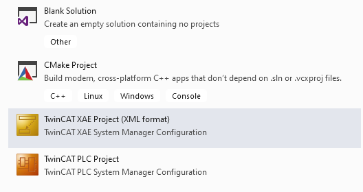 |
| In the Solution Explorer (View --> Solution Explorer), you should see a menu like this one: | 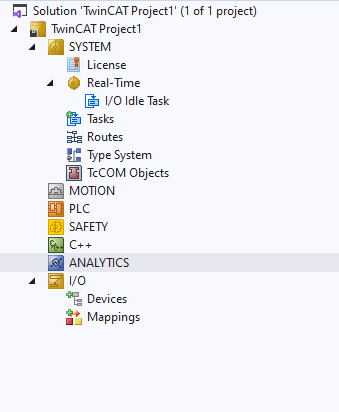 |
| Go to the I/O section and right-click on Devices. Choose Scan. Accept to scan for boxes (connected devices) and accept to Activate Free Run (switch to operative state). |
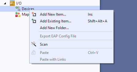 |
| At this point, your scan should have discovered two boxes: the Meca500 and the Bota systems Rokubi sensor, listed underneath an EtherCAT master device (here Device 2, but you can rename it). | 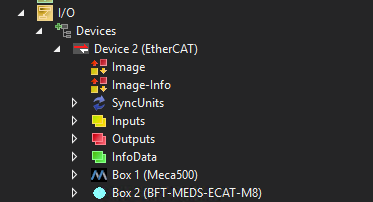 |
| Double click on the master Device (EtherCAT) and choose the Online tab. If everything is working properly, you should see the indices OP next to each device, which indicates that both boxes are in operational mode (OP). The frames/sec data should match the cycle time taking into account the sent number of frames. Additionally, there should be no excessive loss of frame or a CRC error. |
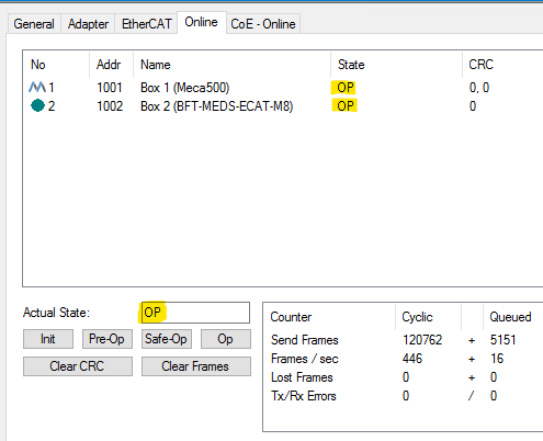 |
Adding the PLC
| Right click on the PLC icon and choose Add New Item. | 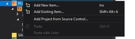 |
| Choose Standard PLC project. | 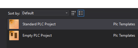 |
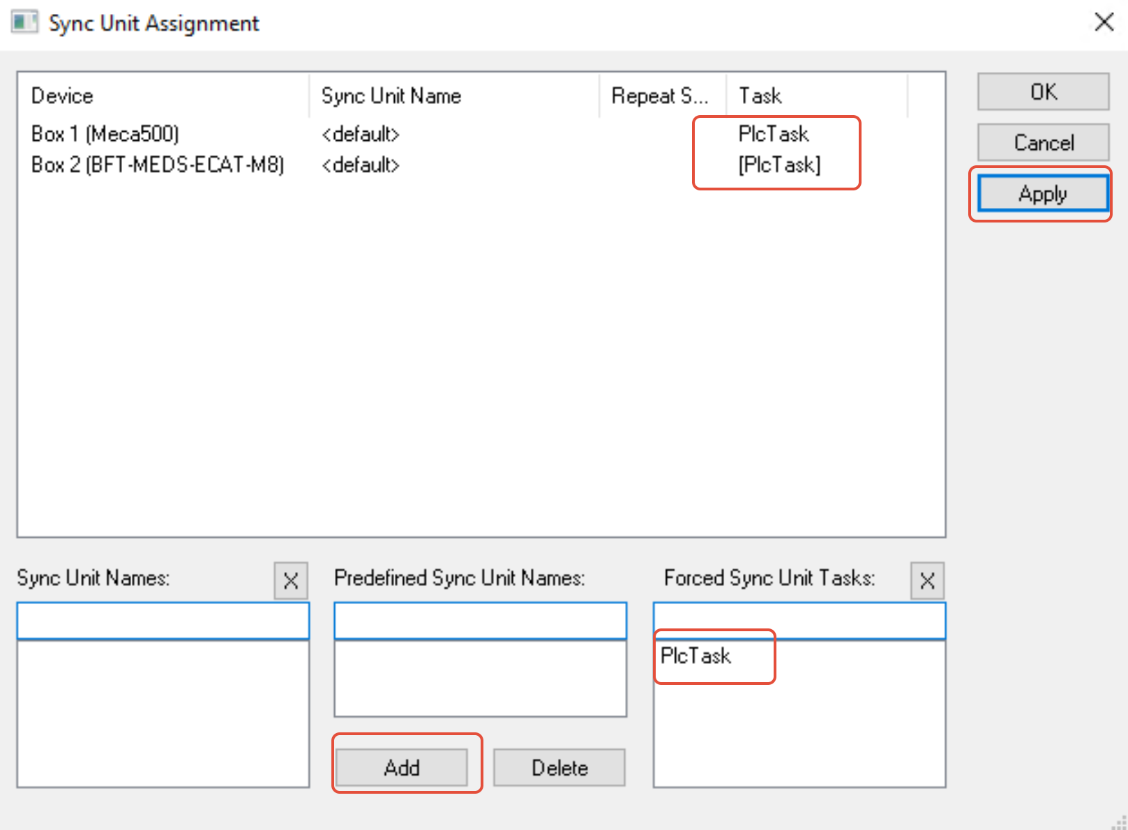
| Associate the devices (boxes) to the PLC by clicking on you Master Device --> EtherCAT tab --> Sync Unit Assignement. Then add the PLC task to each box. | 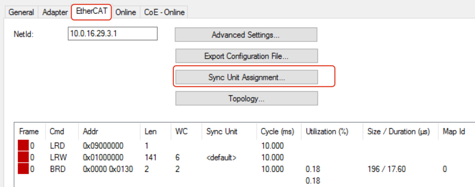 |
 |
Real-time sensor data
This example is limited to connecting the Bota systems Rokubi force torque sensor and to observing the real-time data that is output. A detailed example allowing you to control the Meca500 and better understand how to write code in the TwinCAT3 interface is available here.
| Build your solution, especially if you have added lines of code. |  |
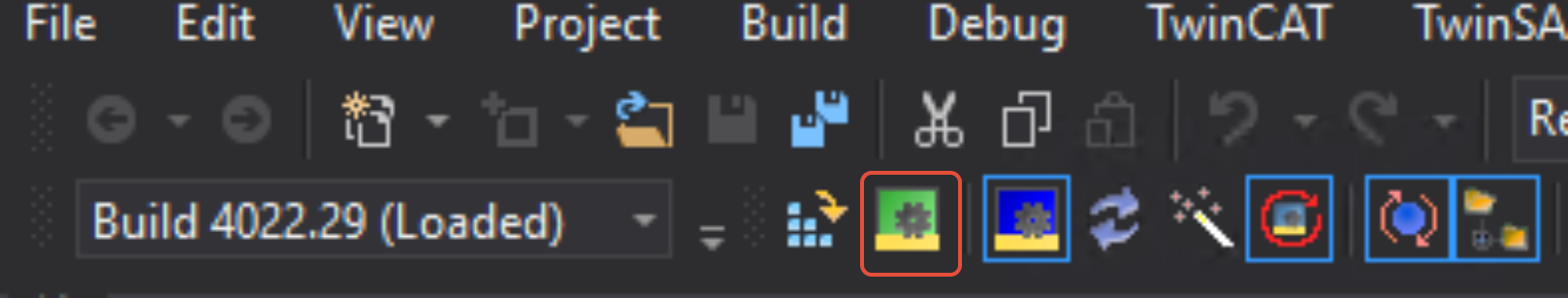
| Activate configuration and restart TwinCAT in Run Mode ( this restart will be done automatically when you click the Activate configuration button). In Run Mode, the Bota systems sensor will start sending data, but we need to configure the sensor's parameters in order to receive the correct values. |
 |
| Double-click on the sensor's box and choose the CoE - Online tab. The CoE (CANopen over EtherCAT) is the method used by the sensor to send its data over the communication lines. In this can you can configure the sensor's force-torque offset, sample rate or temperature compensation, for example. |
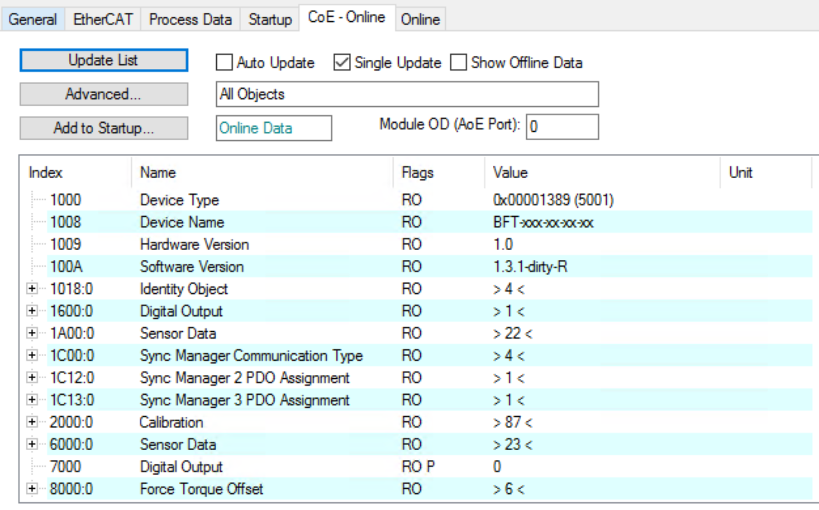 |
In order to obtain correct sensor data, at least two actions are required within the 8010:0 Device configuration menu
|
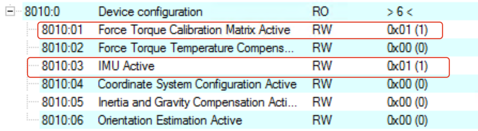 |
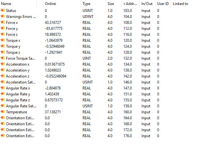
After these steps, you should be able to watch live the data output by the sensor. Apart from the data directly related to the force, torque or acceleration, two variables need to be observed: Status & Warnings Errors. If everything is normal, their value should always stay at 0. If it changes to anything else but 0, then something is not working properly and the sensor data is not reliable anymore.
Please note that these examples are provided as-is by either Mecademic or it's Partners. These can be used as starting point for development and testing but Mecademic or it's partners are not under obligation to provide support and are not liable for any errors or unintended behavior caused by the examples. These examples could be updated over time.
Attachments
Attachments (1)
zip