-3.png?height=120&name=MecaLogo-Black%20(1)-3.png)
This MecaNetwork example features the Meca500 being used with a Sick Flexi Soft CPU0 and an XTI0 IO module. The example program provided can also be adapted to a variety of other Sick safety components and through this safety controller can be connected to other safety equipment. In this example, we feature simple connections of three buttons to use respectively as PSTOP1, SWSTOP and as an external reset button.
This document represent an example of functionality of the Meca500 safety I/Os.
This example is not safety rated and does not replace a safety study for your machine.
It is the clients responsibility to determine the safety requirement of their project.
Components
- Meca500 Robot: Go to link
- Meca500 firmware version 7.0.6 or above: Go to link
- Please note that behavior of PSTOP2 can change with different versions. Consult the Programming guide for your version.
- SICK Flexi Soft Safety Controller FX3-CPU000000: Go to Link
- SICK Flexi Soft Memory Module FX3-MPL000001: Go to Link
- SICK Flexi Soft Safety Controller FX3-XTIO84002: Go to Link
- SICK Flexi Soft USB Configuration cable DSL-8U04G02M025KM1: Go to Link
- DIN Rail (30mm Length or more, depending on components): Go to Link
- DIN Terminal Blocks: Go to Link
- 1kΩ / 1W Resistors FOR Meca500 R3 ONLY: Go to Link
Assembly Steps
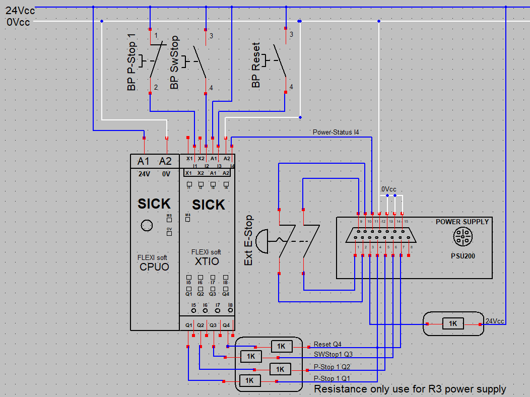
Electrical Drawing
Note that the 1k Ohm resistors are mandatory for the Meca500 R3.
See User Manual Section 7.3.
Software Setup
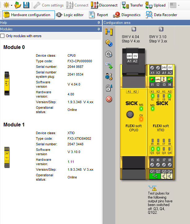
- First, configure your hardware in the Hardware configuration menu. In this example, we use one CPU0 and one XTI0 module. After all your modules were added to your project, you can add all the IOs that will be used in your project. it important to note that you need to disable the test pulse on the outputs that will be connected to the Meca500 PSU.

- Once the hardware is configured, you can program your safety logic in the Logic Editor menu. The example below shows a basic program that contains one P-Stop 1 button, one SwStop button and one reset button. It also use the power status indicator as an external device monitoring input.

- You Can then Connect, transfer, verify and run your program.
Attachements
Attachments (1)
fsp