-3.png?height=120&name=MecaLogo-Black%20(1)-3.png)
This MecaNetwork example features the Meca500 being used with Codesys v3.5 SP19 ControlWin x64 over Ethernet/IP.
This can be used with different your PC using ControlWinx64 Emulated PLC or a Codesys based PLC
This example features a simple Square Move pattern .
Components
Meca500 Robot : Go to site
Meca500 Firmware version 9.3.3 or above is required: Go to site
Codesys : Go to site
Attachments
Mecademic v9.3.3 Codesys EthernetIP : Example Code V9.3.3 EthernetIP
Mecademic v9.3.3 Codesys EtherCAT : Example Code V9.3.3 EtherCAT
User guide: Codesys and Mecademic Function Blocks instructions
Codesys
Software
The purpose of this document is to guide the user in integrating a Mecademic Robot with Codesys v3.5 SP19 patch 2.
Installing the EDS file
Proceed as follows:
1. In the Codesys Environnement, select the Tool Menu, then Device Repository 
2. Click on the Install.. button

3. Select the EDS file from the firmware package.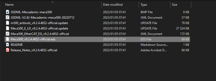
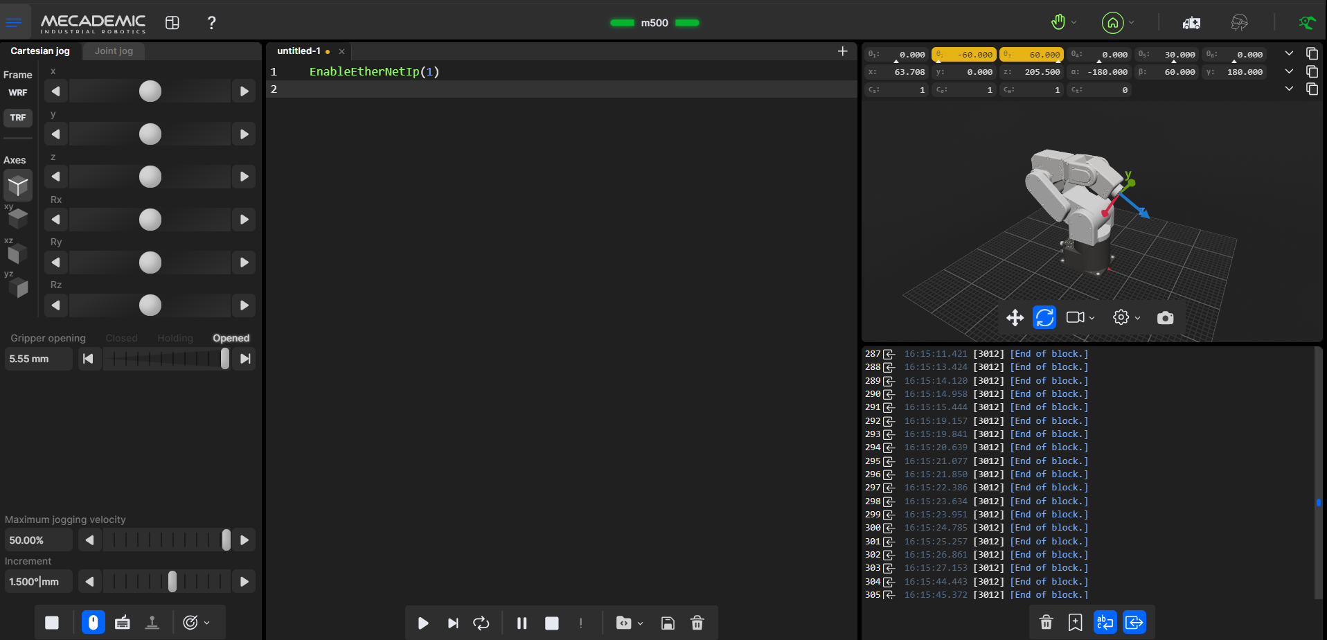
Prior to scanning your network in the Codesys environnement, the following command must be send to the robot on the web interface to enable the network configuration Ethernet/IP.
To enable the EthernetIP protocol on the Codesys PLC, you need to add the Ethernet_IP Scanner.
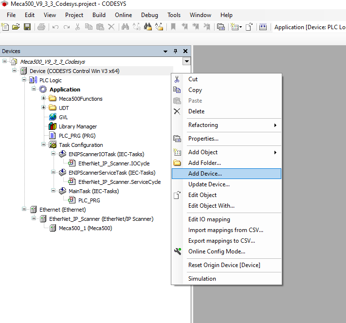
Once the Ethernet IP Scanner has been added,
you can add the Meca500 device.
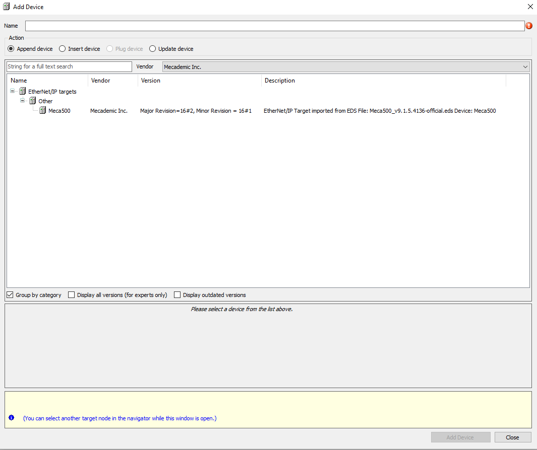
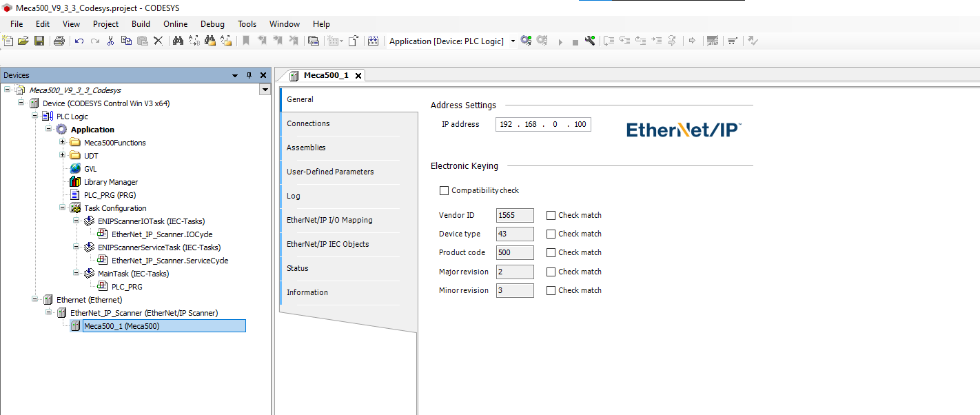
Now, you need to configure the device by giving it a IP address and associating the Input and outputs word to the program variables.
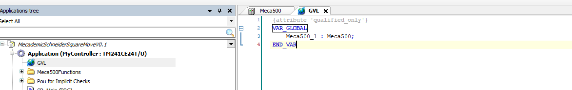
In the Demo program, you will find the User Defined structure for the Meca500
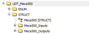
This will permit you to declare an instance of the robot in the Global variables (GVL).
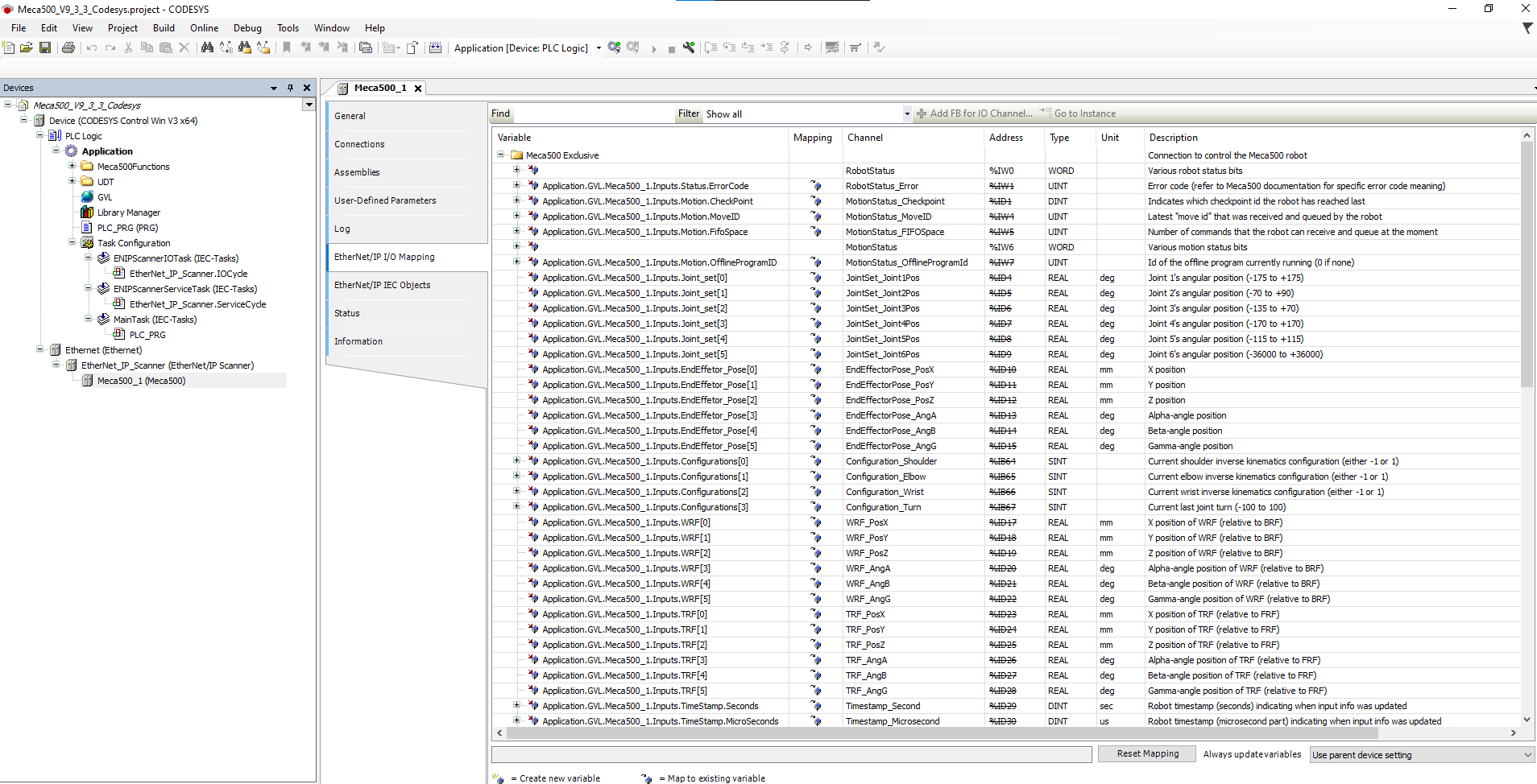
Once you have the robot instance declared, you can associate its Inputs/Outputs in the EtherNet/IP I/O Mapping tabs.
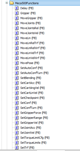
Using the Add-On Instructions
The following Add-On instructions are provided by Mecademic to simplify the usage of the Meca500 with Codesys.
These instructions will be mirroring the commands present in the TCP/IP interface to enable ease of use and standardize the programming structure between the Web Interface and in PLC programs.
Follow the steps below to use the Add-On Instructions in Machine Expert.
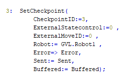
First, select the block that represents the command you want to send to your robot.
Populate the argument(s) field with the values you want to send for the selected command. The command will be sent to the robot on the first scan of the block or when one of the argument(s) values are modified.
If real-time updates are required, sending these instructions by updating the values should be the preferred method. However, it is recommended to update the values before enabling the blocks as this might give better control and prevent multiple instructions from being sent too rapidly if they are not all updated in the same scan.
Once the command has been sent, the sent bit from the block will become true and stay true until one of the arguments is modified or until the block is no longer enabled.
The buffered bit will become true when the MoveID (Internal or External) of the last command received by the robot equals the MoveID of the command sent by the block. When the Buffered bit becomes True it is an acknowledgment from the robot controller that it has received the command and added it to FIFO command buffer queue.

At the end of the Case..Of in the Exemple, you will find this code.
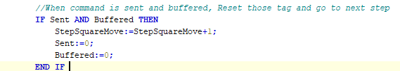
This code reset the Buffered and Sent Flag to False and then allow the sequence to go to the next step, when the Robot has acknowledge the command sent.
To prevent communication problems, it is imperative to send one instruction at a time to a given robot.
We recommend to use a Grafcet like structure, where each step can only execute one instruction.
It is also recommended to only have one instance of an instruction per robot, this facilitate future program debugging.
Motion Commands and MoveID
The way that the robot can identify all of the different commands is with the motion command number. Each command has it’s own unique number. The internal MoveID values of the AOIs are closely related to the motion command values. Since the MoveID needs to be changed every time a new command is being sent to the robot, the add on instruction will alternate between two MoveIDs.
These two numbers will be constructed as such :
|
32
|
xx | 0/1 |
| Prefix | Motion command | Alternate between 0 and 1 |
Below are all the commands, their motion command value and their internal AOI MoveID:
| Commands |
Motion Command value |
AOI MoveID |
| MoveJoints | 1 |
32010-32011 |
| MovePose | 2 |
32020-32021 |
| MoveLin | 3 |
32030-32031 |
| MoveLinRelTRF | 4 |
32040-32041 |
| MoveLinRelWRF | 5 |
32050-32051 |
| Delay | 6 |
32060-32061 |
| SetBlending | 7 |
32070-32071 |
| SetJointVel | 8 |
32080-32081 |
| SetJointAcc | 9 |
32090-32091 |
| SetCartAngVel | 10 |
32100-32101 |
| SetCartLinVel | 11 |
32110-32111 |
| SetCartAcc |
12 |
32120-32121 |
| SetTRF | 13 |
32130-32131 |
| SetWRF | 14 |
32140-32141 |
| SetConf | 15 |
32150-32151 |
| SetAutoConf | 16 |
32160-32161 |
| SetCheckpoint | 17 |
32170-32171 |
| Gripper | 18 |
32180-32181 |
| Gripper | 19 |
32190-32191 |
| GripperForce | 20 |
32200-32201 |
| MoveJointsVel | 21 |
32210-32211 |
| MoveLinVelWRF | 22 |
32220-32221 |
| MoveLinVelTRF | 23 |
32230-32231 |
| VelCtrlTimeout | 24 |
32240-32241 |
| SetConfTurn | 25 | 32250-32251 |
| SetAutoConfTurn | 26 | 32260-32261 |
| SetTorqueLimits | 27 | 32270-32271 |
| SetTorqueLimitsCfg | 28 | 32280-32281 |
| MoveJointsRel | 29 | 32290-32291 |
| SetValveState | 30 | 32300-32301 |
| SetGripperRange | 31 | 32310-32311 |
| MoveGripper | 32 | 32320-32321 |
| StartOfflineProgram | 100 | 31900-31901 |
These unique MoveIDs are useful for troubleshooting and knowing which commands were received or not by the robot. It is also important to not use these internal MoveID when using the external MoveID feature of the AOIs.
External MoveID
The external MoveID feature can be activated by setting the ExternalStateControl value to 1. When this is enabled, the user will need to input their own MoveID in the AOI. The commands will be sent only when the external MoveID value is updated to a new value as with the internal MoveID. This feature can be useful for users who want more in-depth control of their sequence and who want to monitor the commands sent and received by the robot more closely.
It should be noted that this approach needs a careful and thorough understanding of how the MoveID is being used in the robot controller and should only be used by more advanced users. It is also important to note that the values of the external MoveID should never be the same as the internal values of the AOI. If the user tries to input the same value as an internal value the error bit will become true on the AOI.
Please note that these examples are provided as-is by either Mecademic or it's Partners. These can be used as starting point for development and testing but Mecademic or it's partners are not under obligation to provide support and are not liable for any errors or unintended behavior caused by the examples. These examples could be updated over time.
This Exemple was develop with Codesys v3.5 SP19 patch 2 for the Meca500 v9.3.3 over EtherNet/IP