-3.png?height=120&name=MecaLogo-Black%20(1)-3.png)
|
|
 |
 |
 |
-3.png?width=335&height=96&name=MecaLogo-Black%20(1)-3.png)
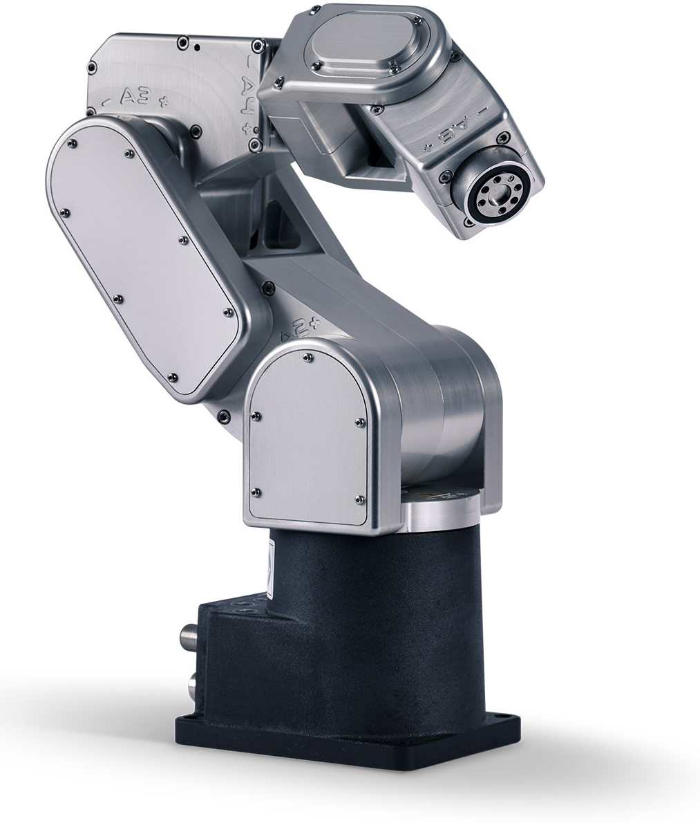
The ATI Delta is a multi-axis force/torque sensor that can be used for a variety of applications requiring contact control between the Meca500 robot and an external element, such as product testing, mechanical precision assembly, grinding and polishing, or even collaborative applications. Given the size of the sensor and the sturdiness of its internal beam structure, the Meca500 can be directly mounted on the top of the monolithic case, using a custom 3D-printed bracket. This type of mounting is very advantageous when the optimal payload capacity of the robot needs to be preserved, while still taking advantage of the sensor's capabilities. This MecaNetwork example serves as a guide to the sensor's integration and testing with the Meca500.
TABLE OF CONTENTS
Components
Hardware
- Meca500 industrial robot: Go to link
- Meca500 firmware version 8.1.6 or above is required: Go to link
- ATI Delta NET F/T Transducer with IP60 protection: Go to link
- NetBox for large transducers with corresponding M12, RJ45 and power cables: Go to link (Manual)
- NET F/T Transducer cable (M12): Purchased with the NetBox and/or the transducer
Auxiliary hardware
- 3D-printed custom bracket: CAD file available at bottom of the page
- 500g payload: Custom piece, not provided
- M6 x 1.0 screws, various lengths and corresponding nuts, when applicable (see Assembly section)
- 5 mm Allen key
Software
- ATI NetFT Java application: Go to this link OR this link
- FT data viewer: Go to link OR contact ATI
Reference documentation
- Network Force/Torque Sensor System Manual: Go to link
- Network Force/Torque Sensor Quick Start Guide: Go to link
- ATI Multi-Axis Force/Torque Sensors Catalogue: Go to link
Sensor specifications
- Precision machined from high-strength aircraft aluminum (mounting adapter) and hardened stainless steel (transducer);
- Measures all six components of force and torque (Fx, Fy, Fz, Tx, Ty and Tz);
- Silicon strain gages with excellent noise immunity, providing a signal that is 75 times stronger than conventional foil gages;
- Near-zero noise distortion;
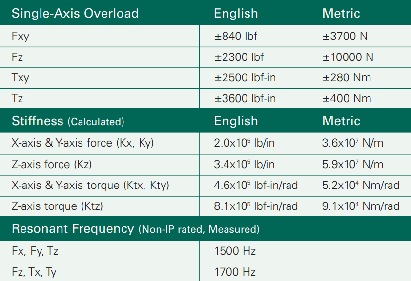
- Increased overload protection: single-axis overload values are 4.1 to 18 times rated capacities;
- High-speed output, up to 7 kHz over Ethernet (using UDP);
- Tool transformation possibility: translation and rotation of the point-of-origin;
- Hardware temperature compensation, optimizing the transducer's accuracy over a range of about ±25º C from room temperature;
- Provides EtherNet/IP and CAN bus communication and is compatible with standard Ethernet, EtherNet/IP and DeviceNet;
- Rated Fxy (±N): 660;
- Rated Fz (± N): 1980 (with SI-660-60 calibration);
- Rated Txy (± Nm): 60;
- Rated Tz (± Nm): 60 (with SI-660-60 calibration);
- Fx, Fy (N) resolution: 1/8;
- Fz (N) resolution: 1/4;
- Tx, Ty, Tz (Nm) resolution: 10/1333;
- Weight (kg): 0.913;
- Diameter (mm): 117;
- Height (mm): 33.3;
- Powered by Power-over-Ethernet (PoE) or by external power supply (11VDC to 24VDC);
- LAN connectivity;
- Configurable web interface, allowing to change system settings and store multiple configurations;
- Real-time Java visualization application;
- Programmable thresholding;
- Programmable low-pass filters;
- Additional parameters (see ATI Sensor Catalogue for more info):
Assembly
power off antistatic wrist or ankle strap
The NetBox installation and configuration are detailed in the ATI Network Force/Torque Sensor System Quick Start Guide. Make sure to follow the direction in the quick start guide before mounting the robot. To connect the Meca500, follow these steps:
- Secure the sensor with M6 x 1.0 screws on your work surface.
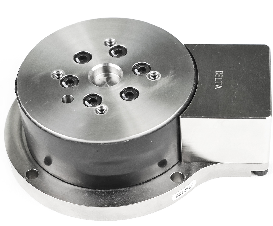
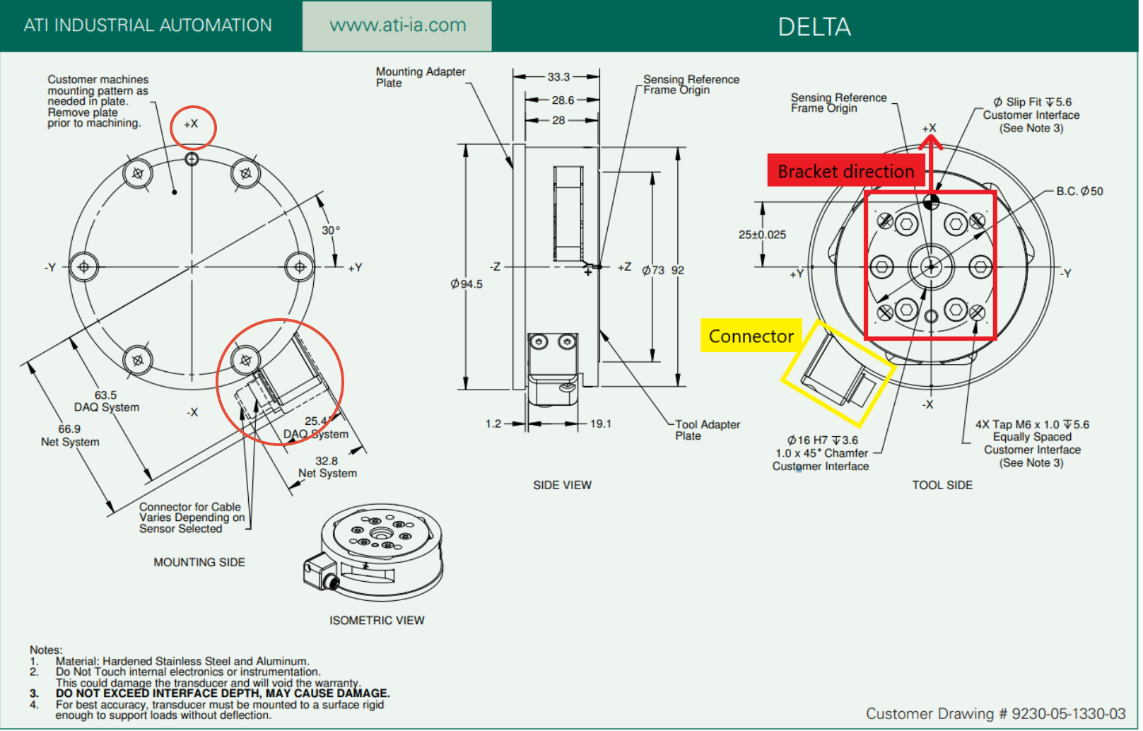
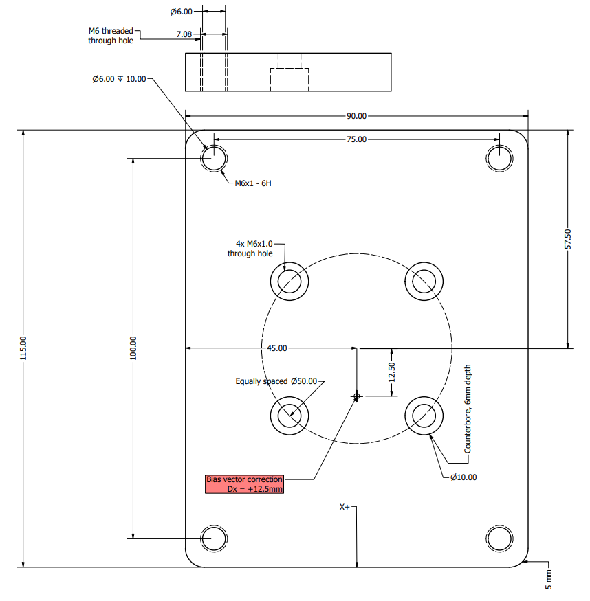
- Mount the custom 3D-printed bracket to the sensor's top surface, using M6 x 1.0 screws with a 5.6 mm maximum length. Keep in mind that the design of the bracket is aligned with the sensor's X axis. When mounted, the bracket may seem off relatively to the sensor's connector, which is normal. If you wish to design a bracket that is aligned with the sensor's connector, you need to account for the alignment in the bias vector while configuring the sensor. For reference, see the ATI Delta drawing below.
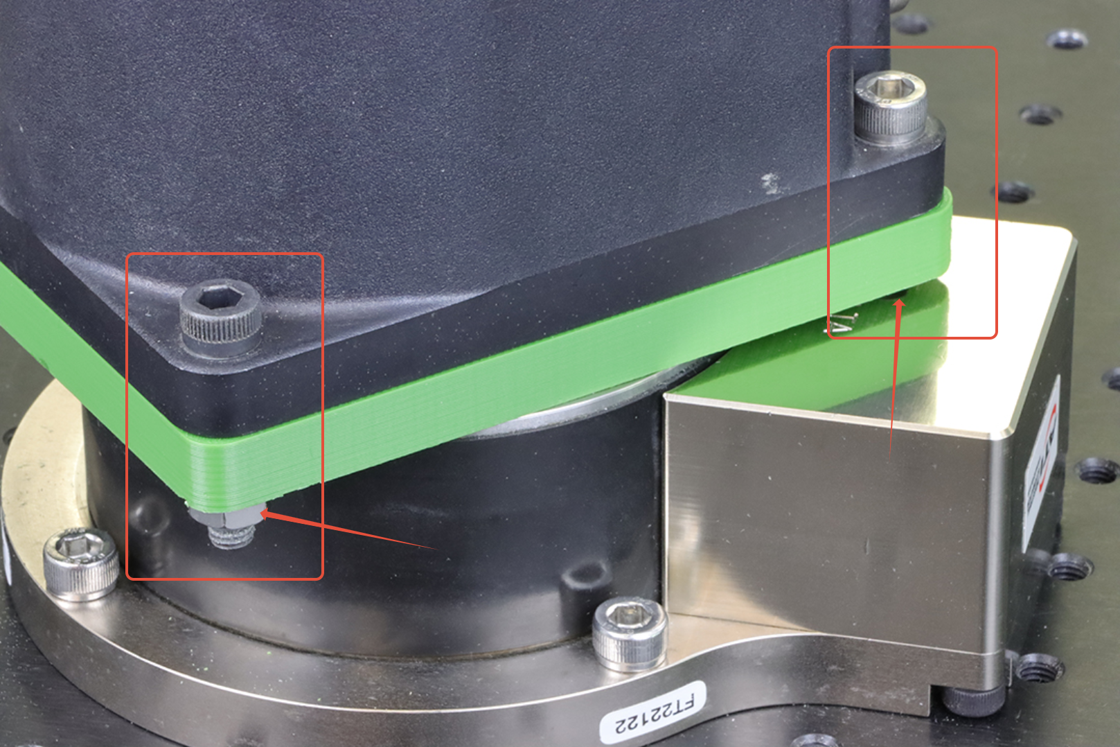
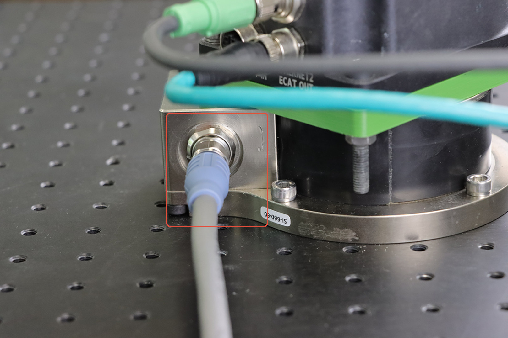
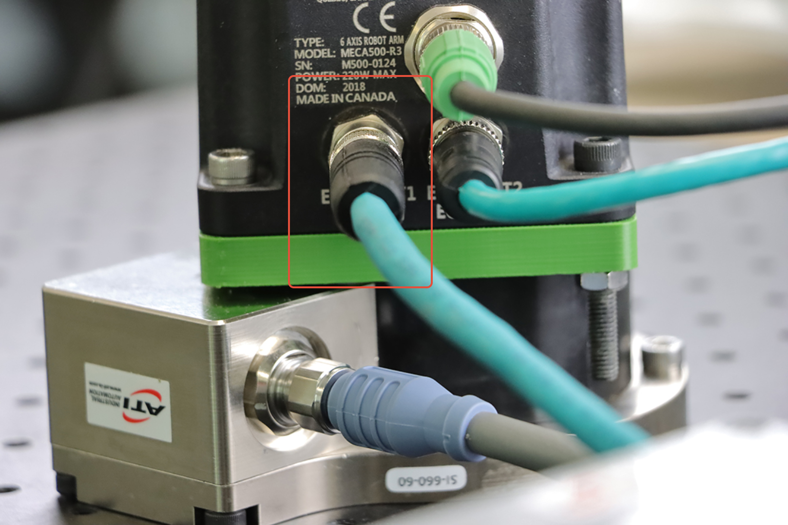
- Mount the robot to the custom bracket. It is to note that three of the M6 screws should be long enough the engage the bracket, the robot's base and a tightening nut. The nut is necessary, since the robot's and the bracket's orifices are not threaded. The forth screw is much shorter, as it coincides with the sensor's connector with our bracket's design, and the orifice is threaded to provide a tighter fit (see images below).
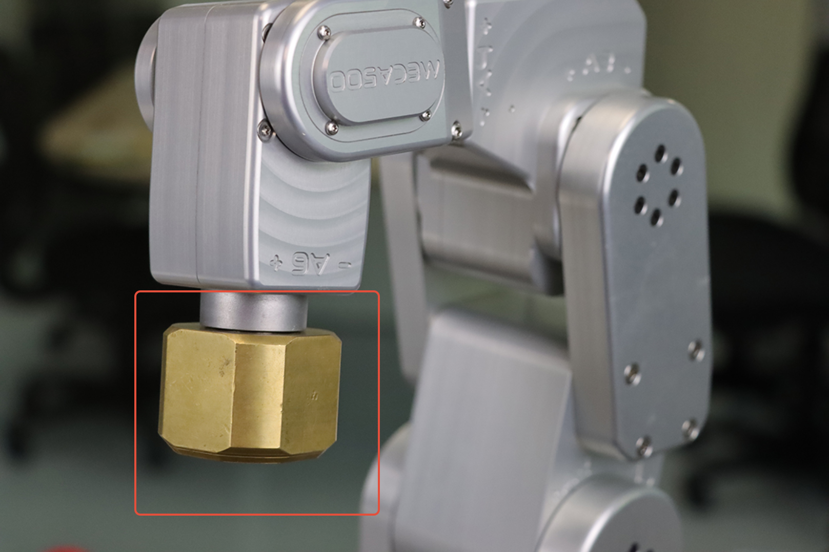
- Mount the 500g payload. As the robot's motors are not activated, the presence of the payload will naturally drag down the robot's wrist, as J5 is free to rotate.
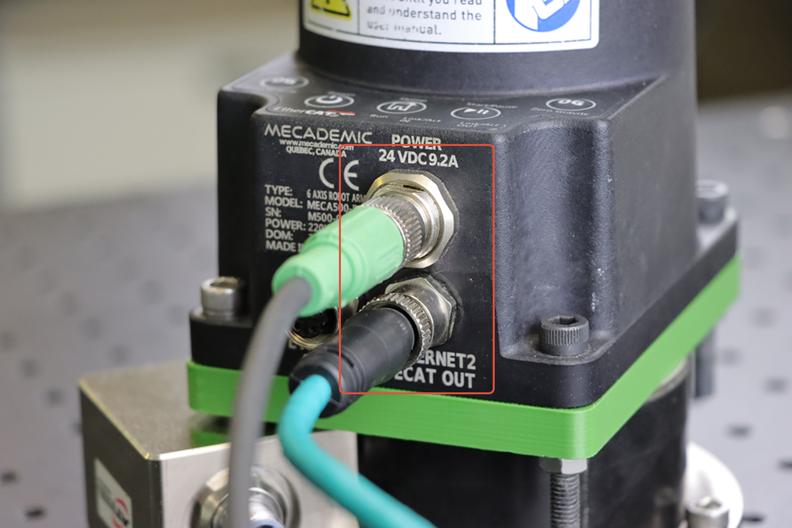
- Connect the Meca500 as usually (Power and M12 cables).
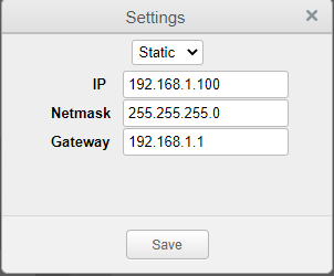
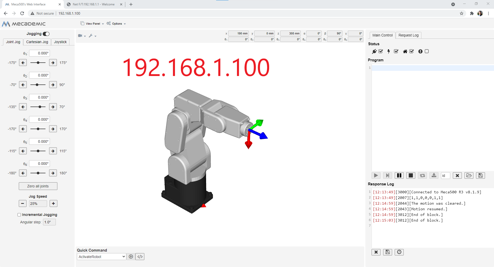
- Change the Meca500's IP address to 192.168.1.100
- Connect, activate and home the robot (for details, see the Meca500 User Manual);
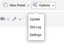
- Go to Options to change the IP address
- Disconnect the robot in order to finish the installation

- Connect, activate and home the robot (for details, see the Meca500 User Manual);
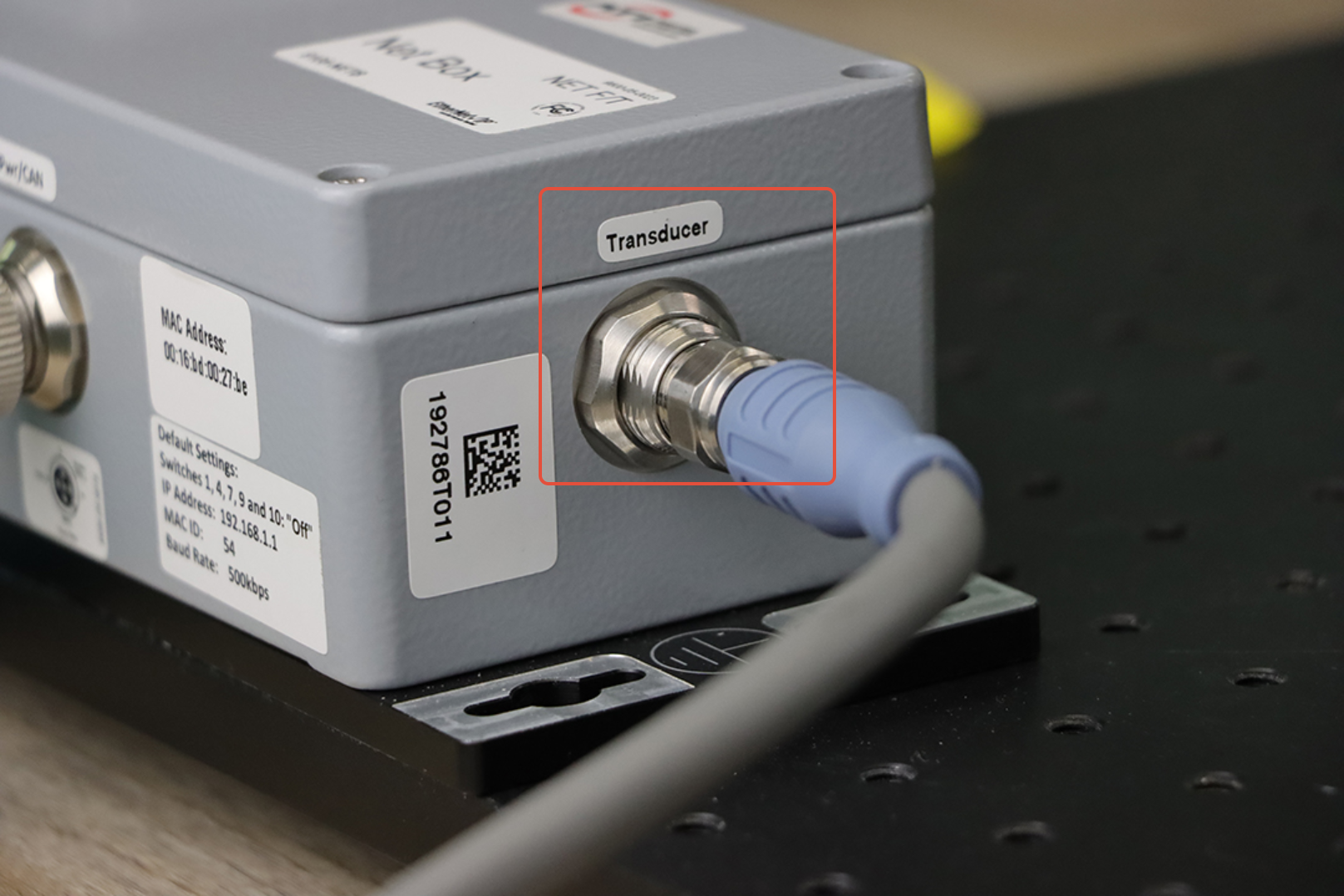
- Connect the Delta sensor to the NetBox's transducer port.
- Connect the NetBox's Ethernet port to the second Meca500 Ethernet port. The Meca500 acts as a switch to the Delta sensor.
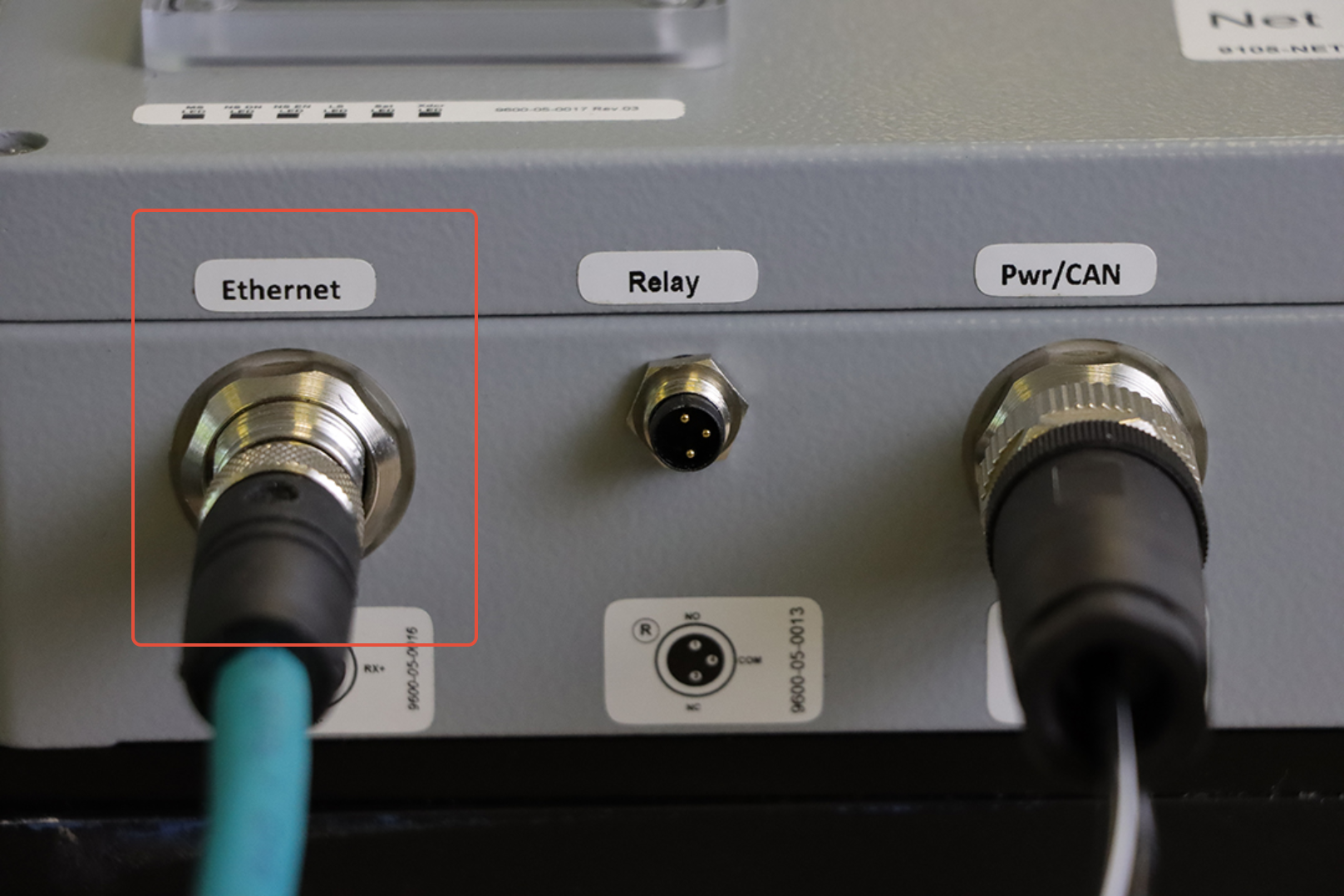
- Power the NetBox
- Open a web browser window with the Meca500's IP address (192.168.1.100) for controlling and monitoring the robot's movements
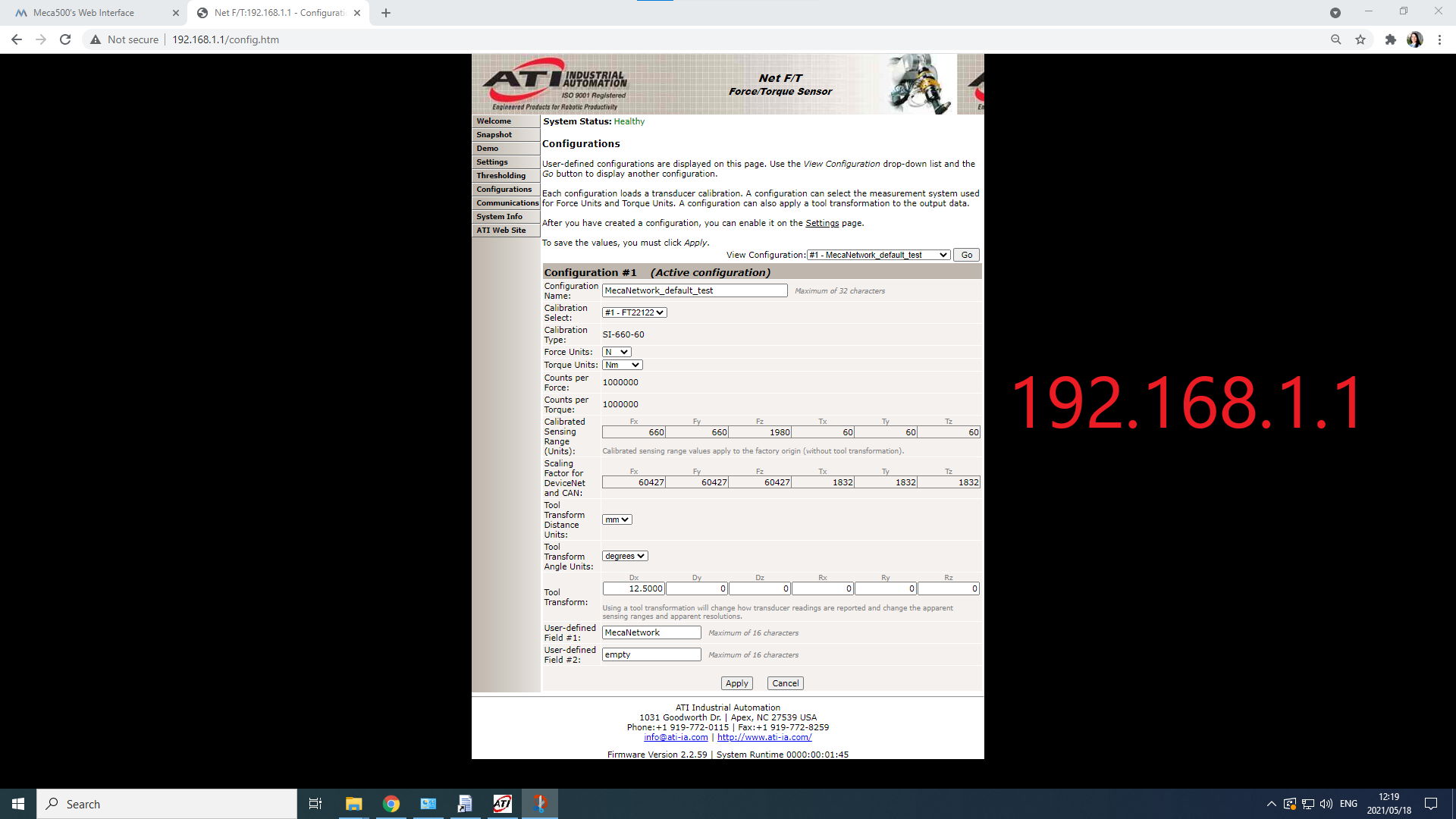
- Open another web browser window with the Net F/T IP address (192.168.1.1) for sensor configuration
- Power, connect, activate and home the Meca500 (for details, see the Meca500 User Manual)
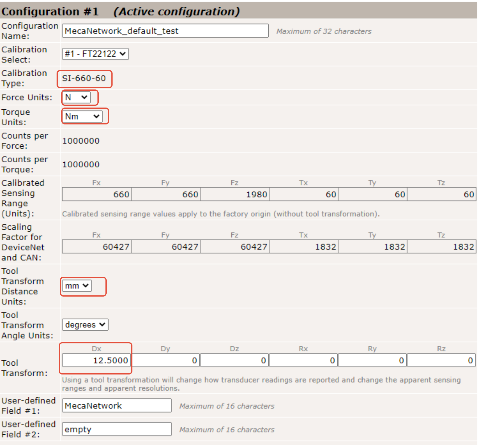
Calibration and configuration
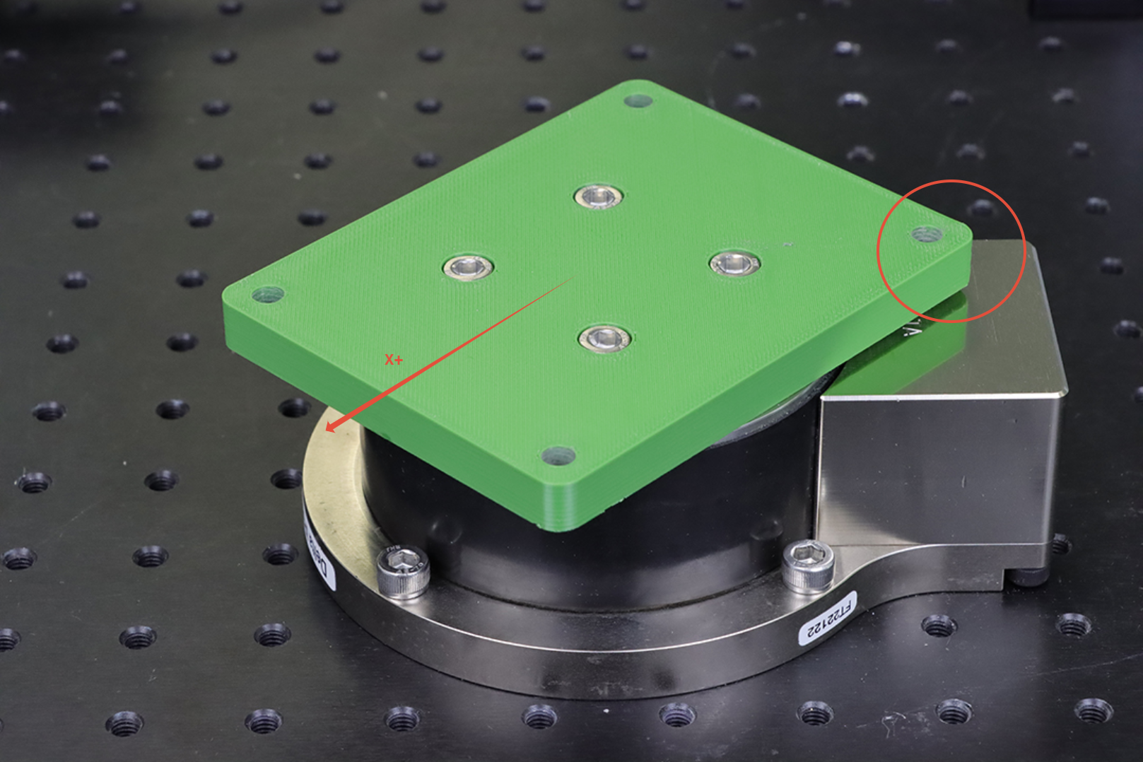
Before configuring the sensor for the Meca500 tests, make sure to complete the set-up steps in the Network Force/Torque Sensor System Quick Start Guide. Then, configure the sensor using the calibration files provided with your ATI sensor, using the desired force, torque and transformation units. The serial number of the calibration files must coincide with the serial number of your sensor. Once calibrated, the sensor's tool transformation can be applied. In this case, only a translation in the X+ direction is needed, Dx = 12.5 mm (see drawing below). Once the sensor is calibrated, you can launch either the ATI NetFT Java application or the FT data viewer in order to visualize and capture the sensor's data. These interfaces allow to take into account the bias vector. Make sure to select the bias button before capturing the data. Otherwise, the data will be incorrect.
Testing
In order to validate the sensor's capacity to support Meca500 applications in most conditions, a test with nominal parameters was executed. Maximum joint velocity of 100% (SetJointVel(100)) and maximum joint acceleration of 150% (SetJointAcc(150)) are used to execute a sequence of extreme positions where the robot is at full extension with a variety of orientations. A payload of 500g is used on the flange of the robot. A very short delay of 0.1s (Delay(0.1)) is imposed between the movements in order to avoid motion errors and reduce the inertia effects on the robots motion components and joints. The Meca500 robot is controlled directly with its web interface.
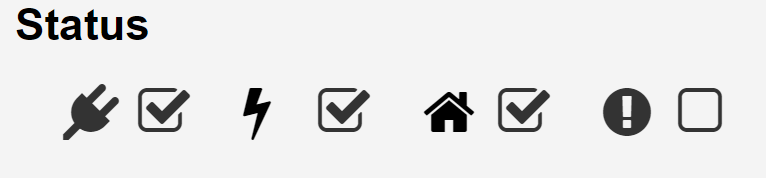
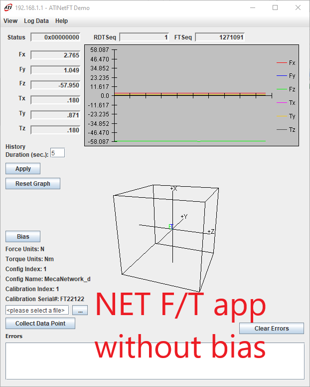
While the robot sequence is executed, it is possible to observe and capture in real time the sensor's output using one of ATI applications. It is important to take into account the bias vector (Bias button) before every visualization or capture, in order to ensure that the data is correct (see Non Biased vs Biased screen captures below). The Mecademic Python API can also be used to capture and visualize the data. Please refer to the Meca500 - ATI Force/Torque Sensor Integration (Using Python) article.

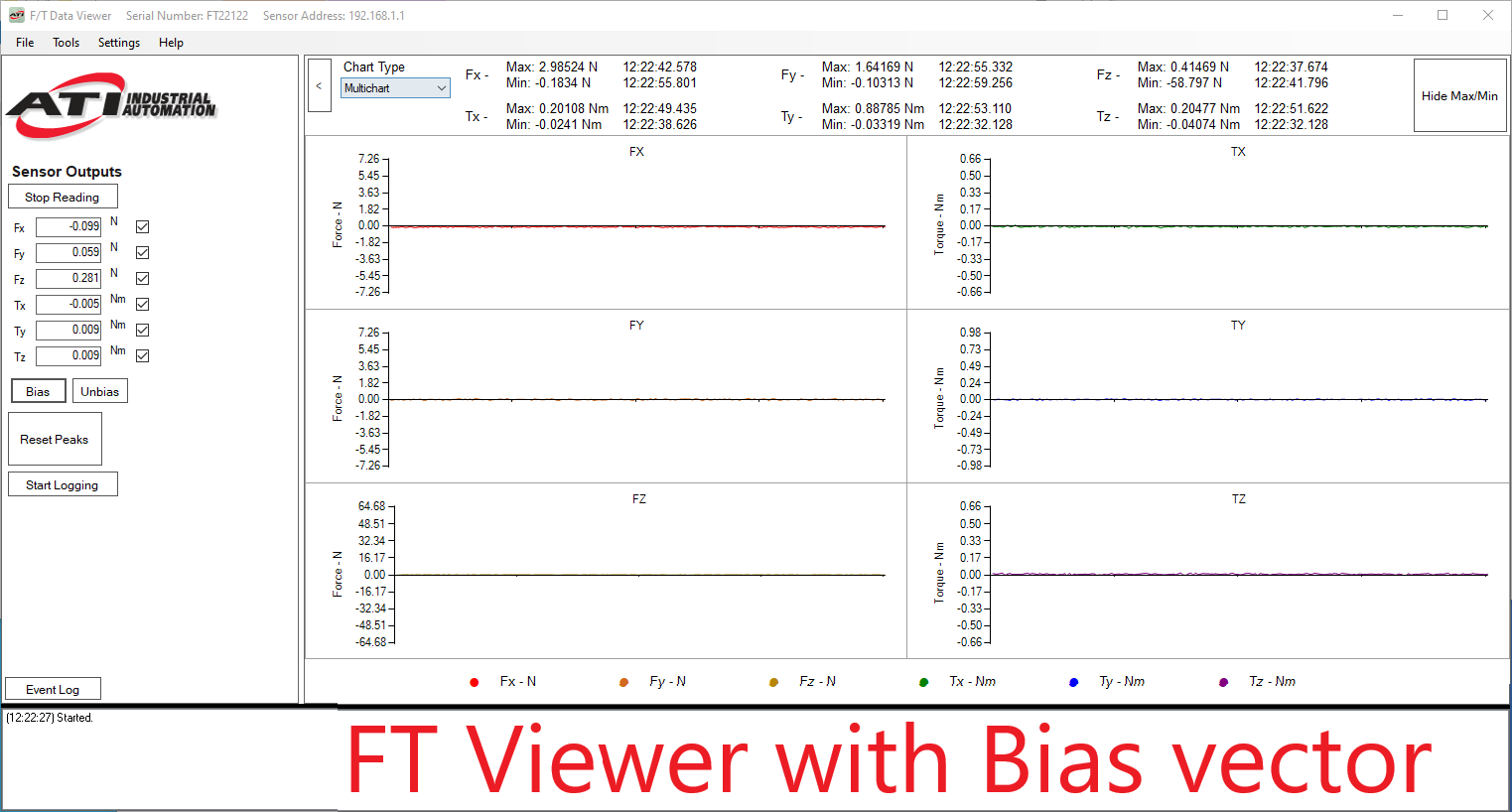

It is interesting to notice that the sensor is sensitive enough the detect a light human touch on its flange. This may be useful for collaborative applications or collision detection.
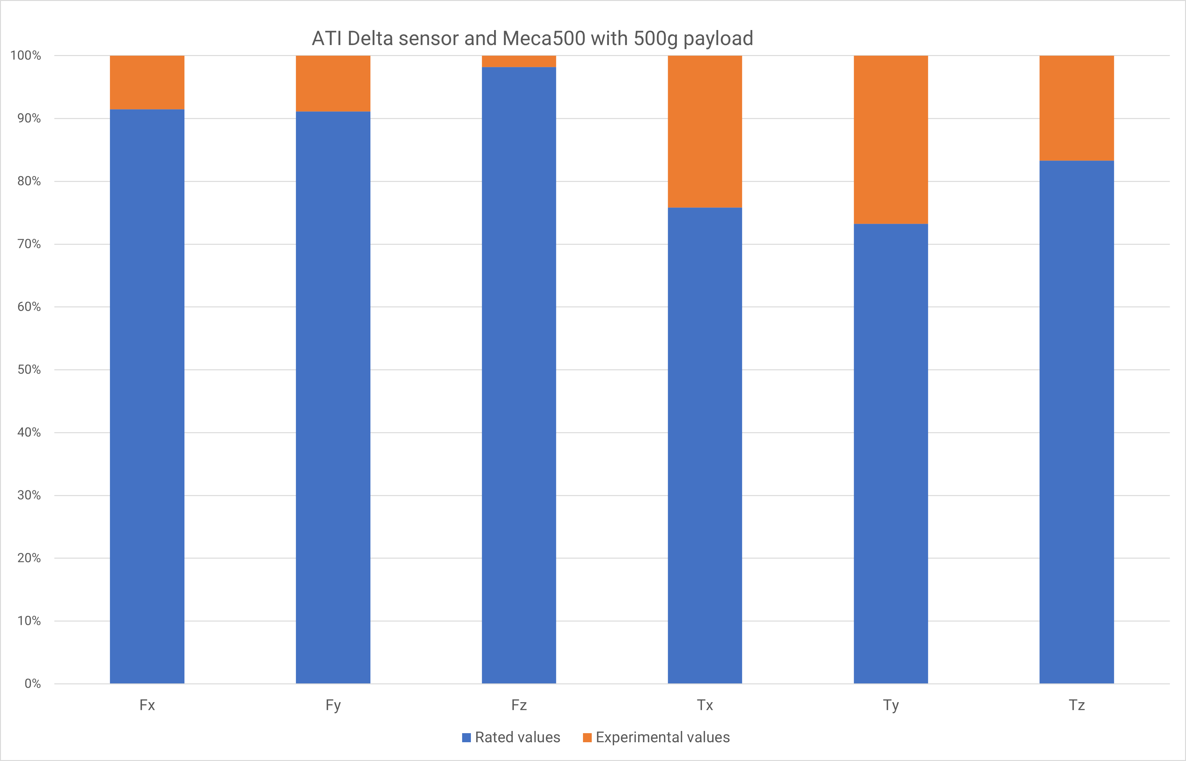
Our tests reveal that the Meca500's nominal functioning stays well within the limits of the sensors capabilities (between 2% and 32% of the rated values). Thus, sensors from the ATI Mini series can also be suitable, as theirs rated values and mounting diameter allow for a similar application. The ATI Gamma series can be interesting as well, but it is important to note that the torque ratings are much lower that the Delta series and could be a potential limitation for the Meca500's actions. ATI provides a useful comparative table here. Smaller sensors can be mounted directly on the flange of the robot thus minimizing the rated force and torque requirements. But with this kind of mounting, the weight of the sensor needs to be taken into account within the Meca500's payload.
Please note that these examples are provided as-is by either Mecademic or it's Partners. These can be used as starting point for development and testing but Mecademic or it's partners are not under obligation to provide support and are not liable for any errors or unintended behavior caused by the examples. These examples could be updated over time.
Attachments
Attachments (2)
stl pdf